VCO – Voltage Controlled Oscillator using Opamps

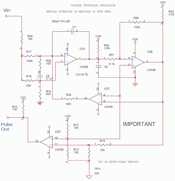
This is a Voltage to pulse converter using opamps for measuring speed or rate from a Tacho Motor mechanical coupled to a Conveyor System.
See the complete circuit in my site to study other sections. The motor DC out is filtered and scaled. Then the clean safe dc is fed to this VCO based on a generic application note design.
The pulses can be used to advance digital counter or mechanical counter using a solenoid driver transistor circuit. The Voltage Vin can be further scaled and fed to a Digital Panel meter to read the rate.
VCO – Voltage Controlled Oscillator using Opamps. LM339 is a quad Comparator.
The complete PDF circuit and other such circuits at my Mixed Circuits Analog with Digital
Tacho Generator – VCO using Opamps
The opamp section of VCO was published earlier for better readability. The full Orcad Schematic in PNG format is here. Many an instance, analog solutions are not only cost effective but very reliable if properly manufactured. They are also as Real-Time as real time can be. Hence never give up on analog for small solutions. It can never be substituted in the front end where the device has close encounters with Real World Parameters.
Even if you have a miniature IoT device, there is a analog front end to it and it gets integrated into the chip too. The designers should always understand how to ensure that the analog front end is robust by using proper protection, filtering or isolation when necessary.
The pulses can be used to advance digital counter or mechanical counter using a solenoid driver transistor circuit. The Voltage Vin can be further scaled and fed to a Digital Panel meter to read the rate.
This is a Voltage to pulse converter using opamps for measuring speed or rate from a Tacho Motor mechanical coupled to a Conveyor System. The motor DC out is filtered and scaled. Then the clean safe dc is fed to this VCO based on a generic application note design.
delabs designs – delabs notes


