Ultrasonic Range Meter
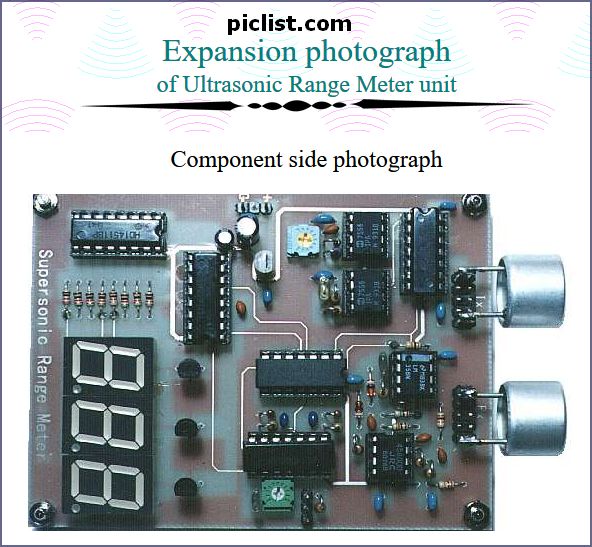
I have attached a document of the circuit explanation of my ultrasonic range meter. But now I want to know if Im going to insert with in series with my 1M ohm resistor for the feed back of the op-amp to tune it for perfect 100db if the pot is not going to cause a bit of inductance due to the high frequency.
Can you please help me with some calibration features/tips I can added into my circuits
Thanks and regards
WS SA
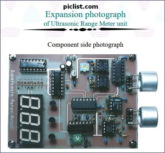
Circuit explanation of Ultrasonic Range Meter unit
oscillation circuit to control the sending-out time of the ultrasonic pulse.
The time of the oscillation pulse can be calculated by the following formula. Actually, with the error of the parts, it is different from the calculation a little.
Circuit explanation for Ultrasonic Range Meter
The ultrasonic signal which was received with the reception sensor is amplified by 1000 times(60dB) of voltage with the operational amplifier with two stages. It is 100 times at the first stage (40dB) and 10 times (20dB) at the next stage.
The following was submitted on June 7th, 2007 at 01:47AM (PDT). message: sent me the ultrasonic distance meter circuit
Mail from MS
Design of an Ultrasonic Distance Meter
There are several ways to measure distance without contact. One way is to use ultrasonic waves at 40 kHz for distance measurement. Ultrasonic transducers measure the amount of time taken for a pulse of sound to travel to a particular surface and return as the reflected echo.
This is the electronic schematic of the homebuilt SONAR. Only one piezoelectric tranducer is used for both tramsmit & receive. This transducer is switched from TX to RX via the four 4016 switches. A high gain amplifier stage & rectifier translates the received echoes into voltage pulses.
delabs

