Switching Battery Charger with L296

This is a a circuit from my Power Supplies Section. There may be some documentation errors in my circuits. If you are used to building and troubleshooting circuits then it is ok.
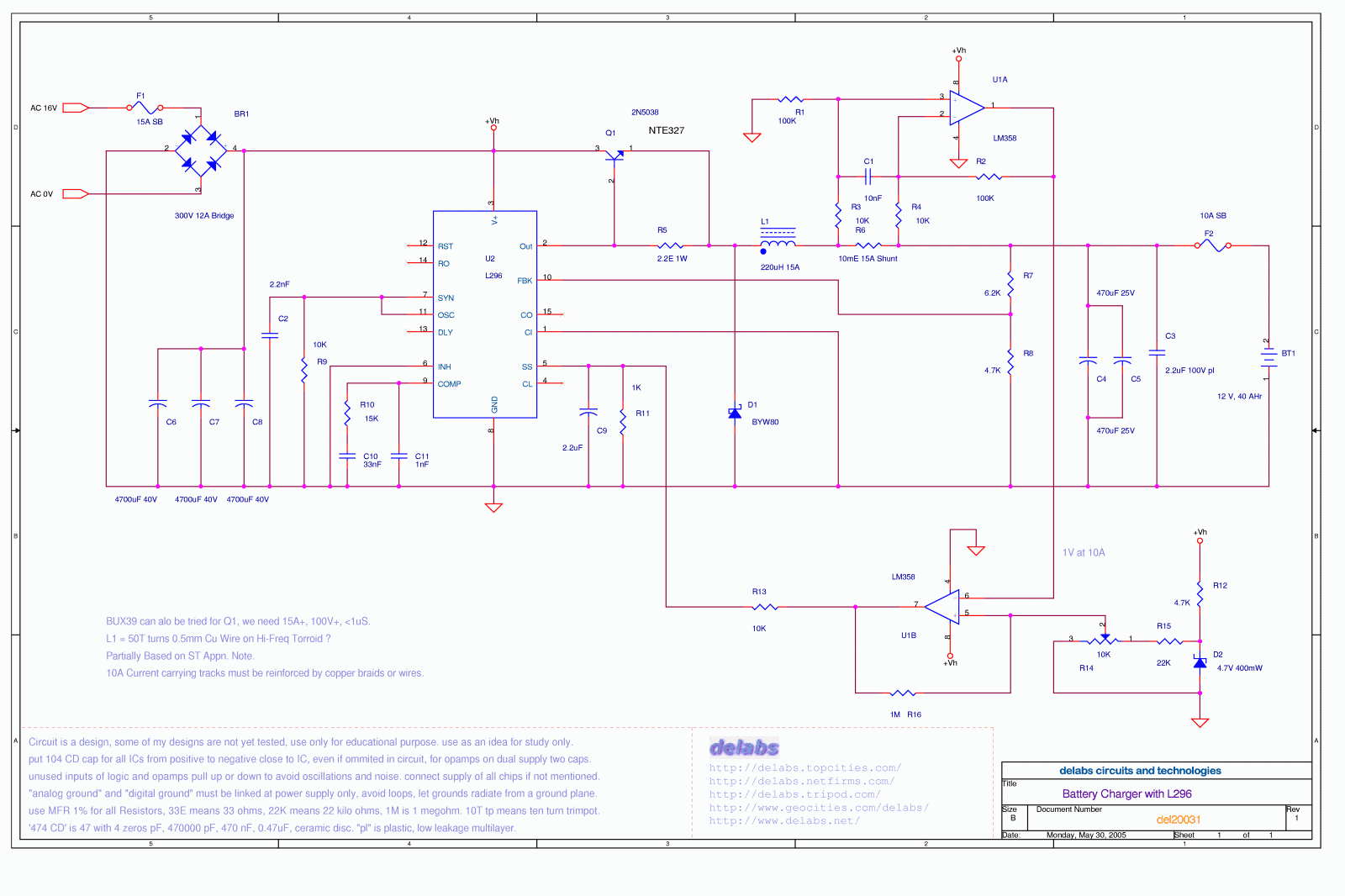
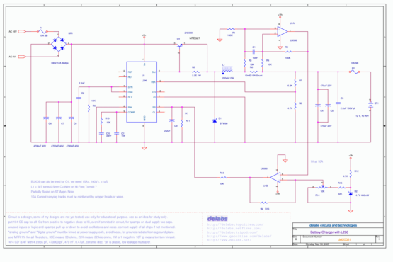
This circuit is derived from an application note of L296, It is a Power Switching Regulator from ST Micro. U1A is wired as a differential amplifier and U1B a High Gain Comparator. C4 and C5 are parallel for lower ESR. Equivalent series resistanc Fast switching diode used is BYW80.
L296 is a switch mode power controller here. In this NTE327 or 2N5038 is used to boost the current output. This transistor is both high current and fast switching. U1A, LM358 measures the load current by reading the voltage across shunt R6 and compared to a current limit setting at R14 using U1B to give a load current control. R7-R8 give a voltage feedback for voltage limit.
Use MFR 1% for all Resistors, 33E means 33 ohms, 22K means 22 kilo ohms, 1M is 1 megohm. 10T tp means ten turn trimpot. “Analog Ground” and “Digital Ground” must be linked at power supply only, avoid loops, let grounds radiate from a ground plane. Unused inputs of logic and opamps pull up or down to avoid oscillations and noise


