Relay Driver – Electromagnetic

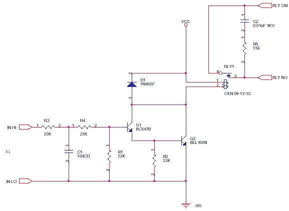
This circuit is a standard way of driving Small Power Relays from Control Signals generated by Logic or Opamp Circuits.
C2 and R5 form a snubber which improves the life of the metal contacts, the contacts can erode due to sparking when switching inductive or even big loads. reduces EMI_RFI.
The Electromagnetic Solenoid Coil is rated by Volts and Ohms. If you choose 12V ensure a stable 12V is provided, more voltage will heat coil, less voltage will cause sparking or will drop out the magnetic holding. A high coil resistance is better as the heat will be less and power consumption of your design is low.

Q2 is any 500mA-50V-NPN device. For a relay drawing 100mA-12V use a 200mA-50V device or better. D1 is a freewheeling diode, inductive kickback diode or snubber or something that stops the coil from zapping the Q2. Q1 and Q2 form a Darlington pair to amplify the low current drive of some CMOS gates.
Infrared Optical Proximity Switch
R2 and R1 is to hold the bases to ground and avoid floating or else they will pick up noise and relay will chatter….. the contacts will spark ……. the motor or heater will fail to work well……… and your product will get rejected ……….. the payments will be held up …… the customer may even ……………………… stop that right now !
R3 and C1 is a dampener for the signal so that quick relay operations can be avoided, this is important if your relay is driving a three phase contactor which runs a huge Motor. C1 can be increased if required. When huge loads are switched on-off in a factory, lots of spikes and drop outs will reset timer and logic circuits, this will turn on off above relay … leading to the load switched by this circuit going on-off. This may even lead to a Oscillation with the spikes as feedback which can cause great trouble during the troubleshooting process. R4 limits current.


