Ohmmeter – Simple Resistance Measurement

Measurement of resistor values in circuit configurations are required to be made often, as these might have changed in value due to various tolerance ranges, and hence could be the cause of faults. Likewise the resistance of components used in a circuit, may need to be known. In such cases the measurement of resistance is a must.

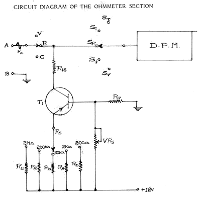
The circuit used for measurement of voltage can be modified to measure the value of the unknown resistance. The principle followed is the measurement of voltage drop across the resistance when a constant current flows through it. In the voltage measuring circuit, the unknown resistance is connected to the same input terminals and the switch SR is operated. Then a constant d.c. current from the collector of transistor T I is passed through resistor R16 to the unknown resistance which is grounded. The voltage drop across the unknown resistor is proportional to the value of the resistance as current is maintained constant. This d.c. voltage drop is measured after proper calibration.
Resistance measurement Current Source.
For the constant current source a high gain, low leakage, pnp silicon transistor (T1) is required. The range selector switch Rs, which connects the positive voltage to the constant current source enables measurement of resistances in 5 decades i.e. 200 ohms, 2 kilo-ohms, 20 kilo-ohms, 200 kilo-ohms and 2 mega-ohms.
According to the range of resistance being measured the switch Rs also selects the decimal point of the displays in the DPM. A resistor R limits the current to the decimal point of the LED displays. Transistor T I is biased by resistor R17 and variable present VR5. As this preset sets the value of current in transistor T1, it has to be adjusted for calibrating the resistance range. Once the calibration is over, the resistance value is directly read on the DPM.
(This is scanned-ocr from my earlier file, some mistakes corrected – delabs)


