Millivolt Meter using a LM3914 LED Dot Display

Here is a easy to read ‘Analog’ Millivoltmeter. Just like the Moving Coil Voltmeter, but does not have that resolution. This gives a easy indication of process progress or parameter magnitude from a large distance. A bargraph is easy on decision making too, compared to a digital readout.
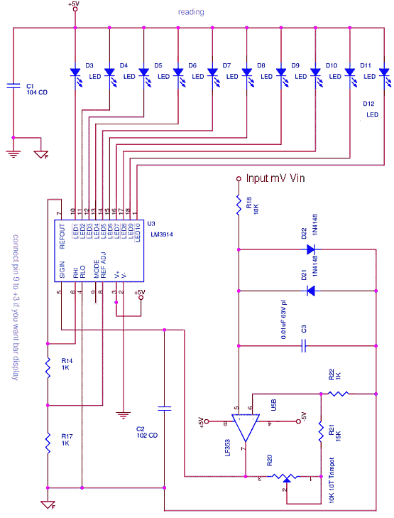
How this Works ? – The analog input in mV – millivolts is fed to R18, RC reduces Noise and the Zener Clamps protect. The LF353 FET Opamp offers High Impedance as a Non-Inverting Amplifier, which nullifies measurement burden, Remember the Moving coil voltmeter loads the measured circuit, causing sizable errors. Then they invented the Vacuum Tube Voltmeter to solve this issue. An FET voltmeter is near ideal, they ought to have inventing this first.
The Zeners and C3 Plastic cap should not leak, even if they do it should be in Pico Amps. Get quality stuff and do a neat job putting them together. To master this leakage and other aspects, try building an Electrometer with CA3140. Another Measurement challenge is uV Microvolt measurements, you will be faced with new glitches in connectors and PCB due to thermocouple effects and contact resistance. A soldered joint near a hot resistor will set up enough thermal gradients and create many thermocouples all over the board. Try to measure 1 Microohm with a 10 Amp pulse or 1 A DC. You will learn many things. Connectors have a craze for the Precious Metal, they act funny if they do not have enough Gold on em.
Once i observed, very low voltages or circuits with nominal voltages but very low currents, cannot break a near invisible layer between the plates of a good connector. A sub-micron coat of corrosion, dust or even some organic deposit, was forming a dielectric layer which was impervious to uV and pA. A good cleaning with a volatile organic solvent solved the problem but messed up other plastics nearby.

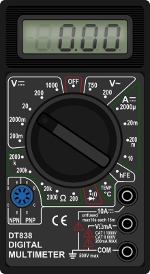
Millivolt Meter using a LM3914 LED Dot Display. – This circuit is a part of my Build a DMM or Digital Multi Meter


