CAD and EDA Tools

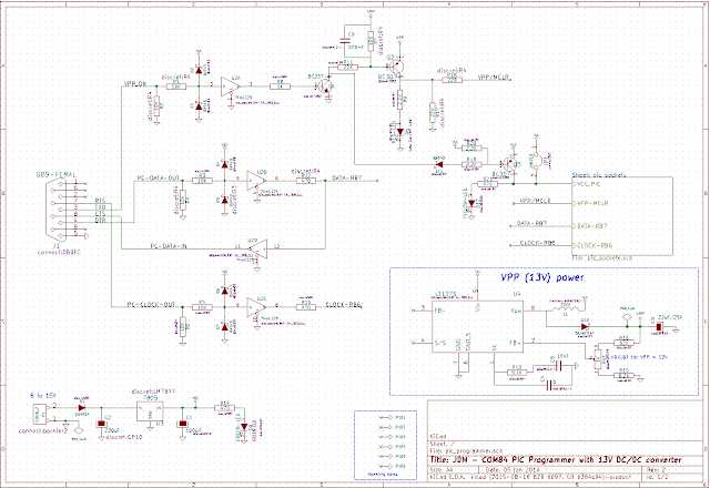
KiCad EDA PCB and Schematic Design
Kicad is an open source (GPL) software for the creation of electronic schematic diagrams and printed circuit board artwork. Designed and written by Jean-Pierre Charras, a researcher at LIS (Laboratoire des Images et des Signaux) and a teacher in IUT de Saint Martin d’Hères.(France), in the field of electrical engineering and image processing.
The electrical rules check (ERC) automatically verifies your schematic connections. It checks for output pin conflicts, missing drivers and unconnected pins.
KiCad comes bundled with a vast library of symbols, footprints, and matching 3D models. They are community maintained so they never stop improving.
Make professional PCB layouts with up to 32 copper layers. This modern tool will help you lay out your board faster. As you draw your track, it pushes forward traces that are in the way. If that is not possible, your track will be rerouted around obstacles.
KiCad consists of ..
- kicad – the project manager
- eeschema – the schematic editor.
- cvpcb – the footprint selector for components used in the circuit design.
- pcbnew – the PCB layout program.
- gerbview – the Gerber (photoplotter documents) viewer.
TinyCAD – Open-Source Schematic Capture
TinyCAD is a program to help you draw circuit diagrams. It comes complete with symbol libraries to get you started straight away.
TinyCAD – Open-Source Schematic Capture
Features to make it easier for you to put your circuit diagrams on your own web-site or adding them to your Word or other documents. TinyCAD supports outputing ciruits diagrams as PNG files.
Can be used to make circuit diagrams that can be fed in to a PCB layout program. You can export from TinyCAD in Protel, PADS, Eagle SCR format. You can also use TinyCAD to create Spice simulation files.
Logisim -Simulate Digital Logic Circuits
Logisim is an educational tool for designing and simulating digital logic circuits. With its simple toolbar interface and simulation of circuits as you build them, it is simple enough to facilitate learning the most basic concepts related to logic circuits.
With the capacity to build larger circuits from smaller subcircuits, and to draw bundles of wires with a single mouse drag, Logisim can be used (and is used) to design and simulate entire CPUs for educational purposes.
Logisim -Simulate Digital Logic Circuits
Some Features
- The wiring tool draws horizontal and vertical wires, automatically connecting to components and to other wires. It’s very easy to draw circuits!
- Circuit layouts can be used as “subcircuits” of other circuits, allowing for hierarchical circuit design.
- Included circuit components include inputs and outputs, gates, multiplexers, arithmetic circuits, flip-flops, and RAM memory.
- The included “combinational analysis” module allows for conversion between circuits, truth tables, and Boolean expressions.
FreePCB is a free, open-source PCB editor for Windows, released under the GNU General Public License. It was designed to be easy to learn and easy to use, yet capable of professional-quality work. It does not have a built-in autorouter, but it can use the FreeRoute web-based autorouter.
Features
- 1 to 8 copper layers
- Board size up to 60 inches by 60 inches
- Uses English or metric units (i.e. mils or mm) for most functions.
- Footprint libraries courtesy of Ivex Design International Inc.
- Copper fill areas
- Footprint Wizard and Footprint Editor for creating or modifying footprints
- Imports and exports PADS-PCB netlists
- Exports extended Gerber files (RS274X) and Excellon drill files
- Design rule checker
- Autosave
Example – Logic Analyzer: This is an open-source logic analyzer called MiniLA
contributed by Bob Grieb of the User Forum. The image on right is the Logic Analyzer PCB.
Some Features:
- Up to 32 channels
- 128 Kb of memory for each channel
- Sampling rate up to 100 MHz (timebase in 1-2-5 sequence)
- Input levels compatible with 3.3V and 5V logic
- Selectable pretrigger/posttrigger buffer size in 8K step
The gEDA project is working on producing a full GPL’d suite of Electronic Design Automation tools. These tools are used for electrical circuit design, schematic capture, simulation, prototyping, and production.
Currently, the gEDA project offers a mature suite of free software applications for electronics design, including schematic capture, attribute management, bill of materials (BOM) generation, netlisting into over 20 netlist formats, analog and digital simulation, and printed circuit board (PCB) layout.
gschem is the schematic capture program/tool which is part of gEDA. Its sole purpose is to facilitate the graphical input of components/circuits. PCB is an interactive printed circuit board editor. PCB offers high end features such as an autorouter and trace optimizer which can tremendously reduce layout time. For custom requirements,
Icarus Verilog is a Verilog simulation and synthesis tool. It operates as a compiler, compiling source code written in Verilog (IEEE-1364) into some target format. For batch simulation, the compiler can generate an intermediate form called vvp assembly.
GTKWave is a fully featured GTK+ based waveform viewer. GTKWave is designed to handle many signals at once, it has three signal searching modes (Regular Expressions, Hierarchy, and Tree) as well as the ability to display data in many different formats.


