Ammeter and Precision Rectifier

Studying current measurement is a prerequisite for many of the measuring techniques. The current parameter mainly specifies the power consumption in a circuit, given the value of resistance. It is found convenient to measure current rather than voltage for knowing power output and determining efficiency. It may be required to measure leakages in circuits at certain times. Hence the measurement of current constitutes a priority.

Measurement of DC Current –
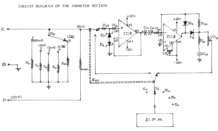
The circuit diagram for the measurement of current (d.c. and a.c. modes) is shown aside. For measurement of current switch SI is operated. The switch S-ad is kept in d.c. mode. This enables the current to pass through a shunt circuit consisting of resistors R26, R27, R28, R29 and R 30. The current ranges are provided in 5 decades i.e. 200 micro-amps, 2 milli-amps, 20 milli-amps, 200 milli-amps and 2 amps. An additional current range that can be read upto 20 Amps is also provided. However, for measuring this high current the green terminal provided on the meter should be used. When a current to be measured is fed to the input terminals of the instrument appropriately, a voltage proportional to the current through the shunt resistor is fed into the DPM which measures the d.c. voltage which in turn indicates the d.c. current being fed.
AC conversion, continuity buzzer test
Measurement of AC Current –
In case of a.c. measurement, the switch S-ad is kept in a.c. mode. The a.c. current path is similar to the d.c. current path in the shunt resistor. However the voltage tapped across the shunt resistor is fed into IC2 which is a buffer. The output of IC2 is fed to IC3 through capacitors C10 and C11. This IC is an operational amplifier acting as a precision rectifier. The output of IC3 is fed to the input of the DPM for measuring the a.c. current being fed to the input terminals. It can be seen that the current measurement is similar to the voltage measurement except that the attenuator chain is replaced by the shunt resistor circuit.
(This is scanned-ocr from my earlier file, some mistakes corrected – delabs)


