0-1V to 4-20 mA Converter

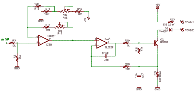
This two opamp circuit converts analog voltage signals to current (sink) signals in a proportional manner. Current signals are more immune to noise and cross talk, hence long wires can be used. Voltage Signal to Current Signal Analog Converter.
Ensure +5/-5 dual supply for chip TL062 IC3. Gnd is common ps ground, let grounds radiate from ground plane in one side of PCB. R3-R8 is an attenuator that may need to be designed or modified.

In output R23 is for protection from shorting of +5V supply, R23 can also go to an unregulated or external. supply upto 24V DC which is referenced to this circuits gnd. More voltage more distance.
Q2 is the current control device, and R22 50E is the shunt for taking a sample of current. 4-20mA in the output (provided suitable load is connected) means 200mV- 1000mV across 50E shunt. This is fed to close loop control system of IC3a inverting pin.
An opamp on this type of feedback tries to drive the output in such a way, so as to maintain both the inputs at same level.
Mini RTD Pt-100 Three Wire Transmitter
If there is 1V at pin 3 and no current is flowing pin 2 is at 0V so output goes positive and drives Q2. this results in a flow of current till a 1V builds across shunt, if it exceeds then output of opamp falls This reduces drive to transistor and hence current reduces. That is the part of V to I conversion with open collector output.
Now we need 200mV to 1000mV to get 4-20mA 4mA is good for 0 as low level measurements are more noise prone. that is the reason 4mA and not 0mA.
Now we need to convert 0-2 V to 0.2 – 1.0 V using IC3B. R14 is a representation of that 200mV offset set by R16 pot. the opamp IC3B adds both the input and this offset to get 200mV to 1000mV. for that the opamp IC3B is an analog computer, summer, subtracter. Try to now calculate the values for that.


