100kHz Half Bridge Convertor – SG3525

This is a SMPS Circuit improved over the Application Note in the book SGS Motion Control Application Manual. This worked well. It helps you learn more about High Frequency Power Supply Design.
100kHz Half Bridge Convertor SG3525 – del50032
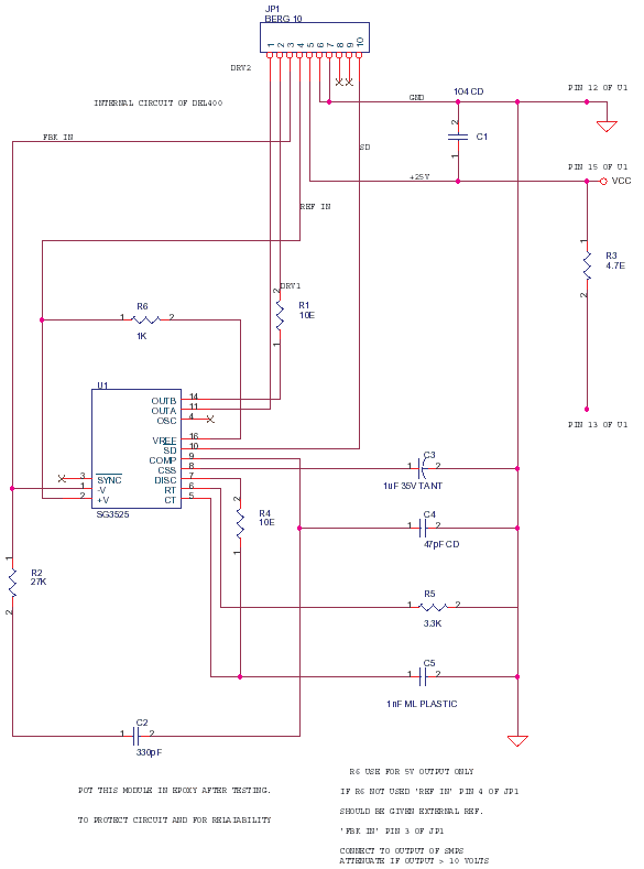
This was the Module that contained the smps chip. It was done to prevent easy replication by other firms. Also to Keep the Signals isolated from the Main board board currents and Corrosion Prevention by impregnating Module in Epoxy. Yet the main board suffered some corrosion even with some coating protection.
Industrial Systems that involve processes like Etching, Coating and Electroplating have to be well ventilated so that electronics around them have some life. Else find ways to package Electronics in Sealed Enclosures with a new plan for Heat Dissipation.
Some Notes Related to the Project
- In main circuit do not link different grounds.
- Main circuit can be used both for 110 AC and 230 AC
- Ferrites are partial conductors use proper insulation before winding.
- For main transformer TRX2 use split bobbin for good/safe isolation.
- Epoxy coated toroids have to be further insulated before winding.
- Line of isolation between primary and secondary circuits should be explicit.
- Primary components like Q1, Q2 tabs R5, R6 etc can give shock take caution.
- Each main module is 500W and can be used in parallel for more current.
- Q1 and Q2 should have appropriate isolated heatsinks TO220 type 50sq cm
- Schottky diodes D5, D6 should have heatsinks TO220 type 100sq cm.
- Diodes D5, D6 eg D83004 are TOP3 packages are used 2 in parallel.
- For 200W and above R2=0.1e 5W in the main circuit fusible ceramic.
- C10, C11… Add 4.7uF 100v more in parallel to reduce ripple.
- C13, C14 can be 250V for better safety margin.
- TRX1 SEC1 and SEC2 dot polarity is anti-phase if same phase danger!!
Magnetics Design
All Transformers Isolation 1kV PRI To SEC / SEC To SEC / PRI,SEC To Core. Use Yellow Mylar Tape Insulation or better for all. Vacuum Impregnate all Magnetics in Epoxy or Varnish. All Power Tracks on PCB reinforce with Copper Braid.
TRX1 Mosfet Drive Transformer
T25.0 MGQ-5L Hitachi – Type Torroid – 100khz Signal
486T250-3C8 Ferroxcube – SEC1 And SEC2 Antiphase
TRX2 Stepdown Invertor Transformer
EC52 Siemens/Hitachi – Can Be ETD/EER Cosmo Ferrites
- PRI1 22 Turns 2 Layers (44 Turns) – 2* #16 Awg(18 Swg) In Parallel.
- SEC1 4 Turns Ct Copper Strap 0.01″ * 0.8″ Copper Strap
Coper Strap/Ribbon used, cause Hi-Freq Skin Effects, PRI 2 Wires paralleled for same reason.
EC52-3C8 Ferroxcube Phillips
Trx3 Current Feedback Trx
T25.0 MGQ-5L Hitachi – Type Torroid – 100khz Signal
- PRI1 1 Turn 4 Amps Max
- SEC1 20 Turns #22 Awg CT.
- Ceter Tap 10T-CT-10T
486T250-3C8 Ferroxcube
L1 Series 60A-80A Inductor
Type EC/ETD/EER EC42 Hitachi – Air Gap In Inductor Core Both Sides
100khz Power IF30-3C8 Ferroxcube – 6 Turns 4*#12 AWG In Parallel
4 Wires Of 12 AWG Twisted & Wound For 6 Turns (Use Less AWG For Less I)
TRX5 50hz Transformer Small
- PRI1 & PRI2 115v
- SEC1 24V 0.2A
- JP2 2-3 Short 230V
- PRI1 & PRI2 In Parallel For 110V
- JP1 1-2 Short 230V 2-3 Short 110V
TRX4
This is A 10mH Common Mode Filter
PCB Layout
- 500W SMPS Copper Side
- 500W SMPS Silk Screen
- 500W SMPS Solder Mask
- 500W SMPS Drill Template
- Main Card – 500W SMPS
- SG3525 Module Card
The PCB of module will be added later, if i locate it. It is small and be designed easily.
Read More
250 W S.M.P.S. with Power-FETs Experiments with the PC power supply encouraged me to an “advancement ” design. The new power supply is also a forward converter with a half-bridge topology. The difference to the modified PC power supply consists in the following items: Two power FETs instead of bipolar transistors used as power switches.


